Bathroom vanity specifications become useful when they show how the parts connect. A cabinet can fit the room, a sink can fit the top, and a faucet can fit the holes. The complete assembly can still have a handle hitting the backsplash or a drain that does not match the sink.
Start with the exact cabinet, sink, countertop, faucet and drain. Read their drawings together, using the same finished wall and floor references. The checks below help you identify a mismatch and decide which missing detail would resolve it, whether you are planning a bathroom, discussing fabrication or comparing a quotation.
Find Out What the Vanity Package Contains
A “vanity” may mean the cabinet alone, a cabinet with a top, or a package with a fitted sink. The faucet, drain, backsplash, mounting parts and connection work may be separate. A product photo does not define the package.
Record the model and finish of each part, along with the current specification and installation documents. A specification sheet shows dimensions and stated features; installation instructions explain the permitted mounting arrangement. A sink cutout template serves a different purpose again: it defines the required opening for the selected installation.
Keep the document version with the product identity. A familiar model name can have more than one version, and a matching finish name does not establish that the fittings connect. If an alternative is proposed, compare its interfaces before treating it as interchangeable.
Match the Faucet Holes and the Mounting Surface
The faucet may mount through the sink's own deck, through the countertop, or through the wall. The sink deck is the ledge around the bowl where faucet holes may be provided. First identify which surface carries the faucet; then check the holes in that surface.
A single-hole faucet, a centerset faucet and a widespread faucet use different arrangements. A centerset design groups the spout and handles on a compact base. A widespread design has separate spout and handle components. Count the required holes and use the selected faucet's drawing for their diameter and center-to-center spacing.
When a three-hole arrangement is described as having 8-inch centers, that refers to the distance between the centers of the two outer holes, not an 8-inch gap between each neighboring pair. Do not infer the hole diameter from that spacing label.
An approved deck plate may cover unused holes when fitting a suitable single-hole faucet to a three-hole surface. It does not move the holes, make the faucet fit a thicker surface or guarantee that the faucet base seals against the surface. Check the actual plate coverage, mounting requirements and space below.
Check the Thickness the Faucet Must Clamp
The mounting stem is the part of the faucet that passes through the installation hole. That stem and its mounting hardware must suit the surface thickness and clamp it securely. Compare the faucet's permitted deck thickness with the actual layers at its mounting hole, including any specified backing or underlay. The decorative edge of a countertop may look much thicker than the surface the faucet actually clamps.
Access matters too. The bowl, cabinet rail or another fitting can obstruct the mounting nut even when the thickness is acceptable. An extension kit is only a solution when it is approved for that faucet and version; it is not a universal fix for every thick countertop.
A wall-mounted faucet uses a different reference: the valve's required position relative to the finished wall, including tile and other finish layers. The visible spout and handle set, often called the trim, may be sold separately from the concealed valve. The valve position must agree with the chosen trim and the sink location before the wall is finished.
Place the Outlet over the Bowl
A faucet's total height does not tell you its outlet height. Likewise, a listed spout dimension may measure from the faucet body center to the outlet, rather than showing how far the outlet reaches into your particular sink. Read the endpoints on the drawing.
Compare the horizontal distance from the faucet's mounting center to its outlet with the distance from that same center to the rear inside edge of the bowl. The difference shows how far the outlet projects over the bowl in plan.
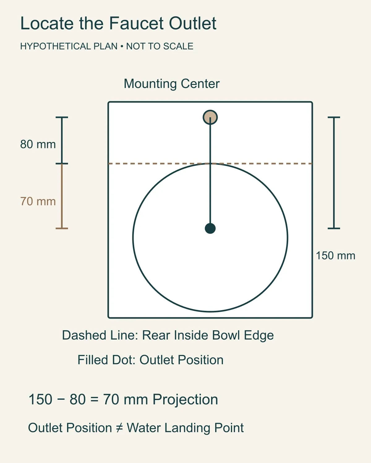
In this hypothetical example, the mounting-center-to-outlet distance is 150 mm. The rear inside edge of the bowl is 80 mm forward of that center. The outlet therefore projects 150 − 80 = 70 mm over the bowl.
Move the faucet hole 20 mm farther back while leaving the bowl and faucet unchanged, and the distance to the rear bowl edge increases to 100 mm. The projection falls to 150 − 100 = 50 mm. The faucet has not changed, but the combination has. This is why a spout that works with one sink layout can feel too short with another.
This calculation locates the outlet, not the exact landing point of the running water. Outlet angle, flow and bowl shape also affect the stream and splashing. Compare the actual faucet and bowl geometry, and test the proposed combination where practical. Do not use one universal “ideal reach” or assume that the stream must always hit the center of the drain.
For a vessel sink, check vertical clearance above the rim as well as horizontal projection. Include the handle's full travel and space for cleaning behind the bowl. A tall body can clear the rim while the outlet still falls too close to the bowl's rear edge.
Match the Sink Overflow and the Drain
Look for an overflow opening near the upper part of the bowl and check the sink's technical description. In an overflow sink, an internal passage carries water from that opening to the drain assembly. The matching drain has openings that accept that flow.
A drain intended for an overflow arrangement is not automatically suitable for a sink without that passage. Incompatible parts can leave a leak path below the sink or fail to connect the intended overflow route. Match the drain's stated application, opening size, sealing surfaces and permitted sink thickness to the selected basin.
Do not assume all vessel sinks lack overflows, or that a drain included with a faucet must fit the sink. The faucet seller may not know which basin you will use. Read the drain instructions alongside the basin drawing.
Also choose how the stopper operates. A lift-rod drain needs space for the rod and linkage behind and below the faucet. A push-operated stopper uses a different mechanism. Neither style resolves a mismatch in overflow configuration or sealing geometry.
The tailpiece is the pipe section below the sink drain that connects toward the trap. Check its size and connection arrangement against the proposed trap and site piping. A nominal drain size alone does not identify all the threads, seals or adapters in that connection.
Check Below the Top Before Finalizing the Openings
An undermount sink needs space for its outer rim and specified mounting parts, not only the visible bowl. The cabinet's rails, sides and drawers must leave room for those components. The countertop fabricator—the business that cuts and finishes the top—also needs the selected material's requirements for openings, remaining material and support.
A sink's outside dimensions are not a substitute for its current cutout template. The exposed or covered portion of an undermount rim must match the agreed detail. Do not scale a small catalog picture or use another basin's template because the bowls look alike.
Plot the drain, trap and shutoff valves inside the cabinet. The trap is the drain fitting that retains a water seal; the valves stop the water supply for service. Show both where they fit and how someone can reach them. A drain that clears the bottom of the bowl may still collide with a drawer farther down.
For the water supply, record the faucet's connection type and size, supply-line requirements and stated operating conditions. Have the plumbing designer or installer compare them with the site system and local requirements. Thread type, available pressure and the permitted drain route cannot be inferred from a matching finish or an overall cabinet dimension.
Keep One Configuration Record
Use one assembly reference, such as V-01, to keep the chosen parts and drawings together. The table below is a record structure you can adapt; V-01 is an example identifier, not a product offered for sale.
| Part or Interface | Record With the Assembly |
|---|---|
| Cabinet | Model, actual dimensions, finish, internal layout and installation method |
| Sink and top | Basin model, mounting type, top construction, current cutout template and agreed rim detail |
| Faucet | Model and finish, mounting surface, holes, permitted thickness, outlet position and handle travel |
| Drain and supply | Overflow match, drain and tailpiece details, trap arrangement, supply connections and service access |
| Site and documents | Finished wall and floor references, pipe locations, drawing revisions and responsibility for each unresolved interface |
Consider a hypothetical V-01 proposal with a top drilled for a three-hole faucet. A later substitution offers a single-hole faucet and an included drain. Two questions remain separate: can an approved plate and mounting arrangement suit the existing top, and does that drain match the basin? The word “included” answers neither.
The resolution might be to retain the original faucet, approve a suitable single-hole arrangement, or revise the top before fabrication. The selected drain may need to be changed independently. Update the part list and drawing together so the fabricator does not cut an earlier hole pattern for the revised faucet.
When quotations are involved, assign who supplies each component, who cuts the openings, who installs the basin and who completes the plumbing connections. Identify who coordinates changes across those parties. An excluded drain or an unpriced pipe alteration is a scope gap, not a zero-cost item. The Building Materials Quote Comparison Worksheet can help organize those commercial differences.
Before fabrication, the useful outcome is an agreed configuration with current part references and resolved cutting information. Before installation, it also needs verified site dimensions and compatible support and plumbing arrangements. A complete-looking list becomes a coordinated specification only when the connections between its parts have been checked.
For width, depth and the complete room footprint, see the Bathroom Vanity Dimensions Guide.